 DXpeditions
| Bletchley park morse decoder | |
Using a teensy 2.0++
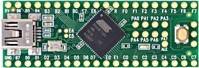 The morse key is connected between C6 and C7
The speaker is connected between D7 and B4
and the following code is used
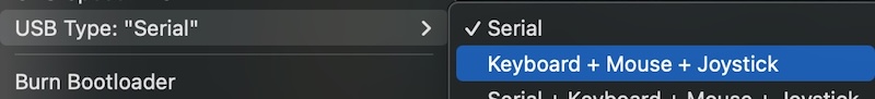
Important to change the settings in the Arduino IDE to enable keyboard mode for the teensy 2.0++
| |
| By: marios added:03-05-2025 07:03 |
| How to control ICOM DVR with contest software (OTRSP) | ||
NThis hack should work with any software that supports OTRSP protocol. (or MKII protocol)
The hack is based on the following fact about DVR enabled Icom radios:
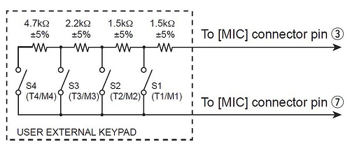 Although you could use a series of resistors and switching transistors, this solution is NOT cool!
A cooler solution is to use a digital pot such as the MCP4231 controlling it via a simple arduino like the nano with a USB serial port. This digital pot has 2x 0-10K resistors in linear 128 steps. When connected in series you can get 0-20K and the control is via SPI
(mode 0 and mode 3 supported)
Here is the schematic!
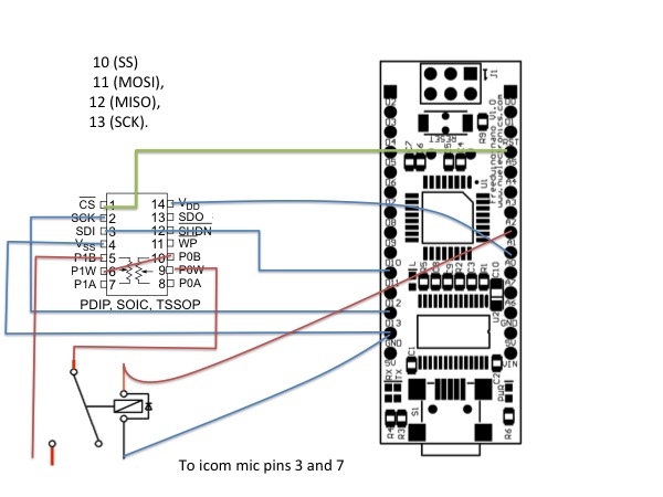 You can use any digital or analog pins but configure the correct one in the code
I am using A0 for VDD and A5 for CS (=Chip Select).
The code is simple:
Reset
Then switch on the pot (A0 HIGH) 5V to its DCC
Look out for the Serial commands from the software:
KP1, KP2, KP3 or KP4 or KA (Abort) as per OTSRSP
Put the resistance to the right level using SPI
Wait for 50ms for ICOM DVR to detect that
Put the resistance back to 20K using SPI
Listen to serial port
It uses MKII serial commands for now as win-test doesnt as yet support OTRSP voice keyer commands.
This code has been tested with an icom 756 pro III
| ||
| By: mnicolao added:14-03-2012 19:45 (modified: 29-03-2012 14:58) |
| VS1053b and arduino playing a file | |
Next step how to play a file from a FAT32 formatted SD card
eg 1.mp3
| |
| By: mnicolao added:04-03-2012 18:45 |
| Playing hello using VS1053b and arduino | |
Having had a successful sign test the next step is to see if we can play the hello buffer
Here is the code:
| |
| By: mnicolao added:04-03-2012 01:55 |
| Interfacing the arduino with the VS1053b shield | ||
This has been a great challenge for me and I hope that I would be able to solve the interfacing problem of the arduino (IDE v1.0) with the VS1053b based shield such as this one
OK lets start by getting the sine wave test working:
For this to work here is the pseudocode:
Here is the working example using my class
| ||
| By: mnicolao added:03-03-2012 23:08 (modified: 04-03-2012 01:03) |
| Connecting a PICAXE OLED LCD to arduino | ||||||||||
I recently bought this LCD from picaxe.com (AXE133Y). I was impressed by its quality and price and most importantly, I thought I could use it with my arduino projects by sacrificing only 1 pin.
Unfortunately this was not possible straight out of the box!
It seems that the 18M2 Picaxe chip prefers serial communication using inverted signals! The arduino uses normal signals so without modifying the firmware it is not possible for these devices to talk.
Modifying the code was straight forward but uploading it was simply a nightmare as I did not have the picaxe programming cable which looked exactly like my ftdi TTL-232 cable. There are 2 important differences:
1) The picaxe cable uses inverted signals whereas the FTDI cable uses non-inverted ones. The problem can be solved by using this program [use instructions here]
2) The wiring of the two cables is different
Finally here is the code I used for the firmware (all credit to www.picaxe.com
To talk from arduino you can send the following commands
etc etc | ||||||||||
| By: mnicolao added:08-12-2011 00:13 |
| A morse decoder for arduino |
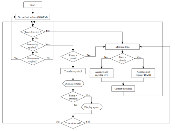
An algorithm for decoding Morse code with arduino, some inspiration from this article
From wikipedia:
The perfect morse code needs:
The real morse code has a dot:dash ratio of 2.5:1 to 3.5:1 Firstly, we need to determine this ratio:
If the inter-element gap length is denoted as Tm and dot as Td:
Use the first ten time lengths to calculate Tm and Td
High Level Time=H_TIME [ie not pressing]
Low Level Time=L_TIME [ie key pressing]
blank a dot/dash array
R=H_TIME[n]/Tm
If (R with 0.5 and 1.5) {
S=L_TIME[n-1]/Td
if (S within 2.5 and 3.5) {
dash
} else {
dot
}
advance to next element in dot/dash array
} else if R (within 2.5-3.5) {
we have a letter space hence decode array
}
Another algorithm obtained from here can be summarised in this diagram
 |
| By: mnicolao added:01-12-2011 22:20 (modified: 03-12-2011 16:52) |
| Controlling the MCP4231 Digital Pot with the arduino | ||
Using the datasheet here is how to control the MCP4231
129 steps (0-128)
10K
For arduino Mega: use
int ss1 = 53;
int clk = 52;
int mosi = 51;
| ||
| By: mnicolao added:02-03-2011 23:16 (modified: 02-03-2011 23:18) |
| SO2RDuino - A USB SO2R Box by K1XM |
K1XM has just published details of how to build an SO2R box using the arduino platform in NCJ.
Some of the features are:
The full article can be found here |
| By: mnicolao added:01-08-2010 11:44 |
| Band data | |||||||||||||||||||||||||||||||||||
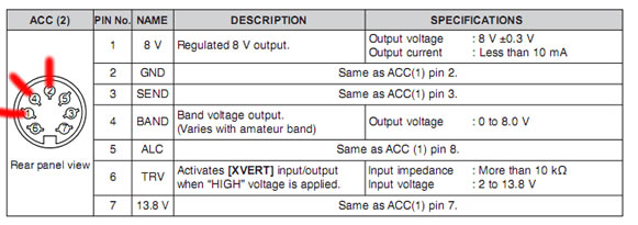
Icom rigs have their own unique way of providing information to external rigs based on the current band. This information is provided on a single pin on the ACC-2 socket by varying the voltage from 0-8V (see figure below).
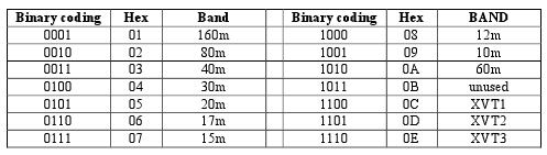
 Most peripheral equipment use the ubiquitous YAESU band data method as follows
 This project uses an arduino to read the voltage from the ACC2 pin, determines the band and then converts it to a YAESU band data to use with the many peripherals that support the latter. As the arduino can sense up to 5V (TTL level) and the icom outputs up to 8V, a voltage divider is required to fool the arduino analog pin that 8V is 5V! Here is the schematic:
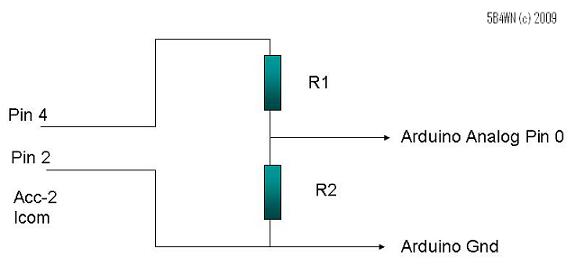 R1=6K
R2=10K
Use analog Pin 5 on Arduino
Use Digital Pins 9, 10, 11, 12 for YAESU output DCBA
You can use the Pin 1 for ACC2 to supply the voltage for the
arduino
So this voltage divider converts the Icom voltages as follows:
So once the circuit is complete, you need to program this using the arduino development environment. Find more about this here
Copy and paste the following code:
Arduino Code:
I have built this using an arduino RBBB and a FTDI programming cable. I have tested it in 3 contests now and it has worked without fail.
WA4SIX has modified the above code for BCD see here
| |||||||||||||||||||||||||||||||||||
| By: mnicolao added:24-07-2009 13:14 (modified: 21-04-2020 20:20) |
